Duct Bank Design Guide

Backfill evenly around duct with clean dry earth and mechanically tamp in 12 lifts.
Duct bank design guide. Where elbows are required to transition from horizontal to vertical for stub ups use rigid steel conduit sweep elbows. Duct banks is 3 feet below grade measured to top of ductbank. Use walls of trench to form side walls of duct bank where soil is self supporting and concrete envelope can be poured without soil inclusions. Duct banks are to terminate in a service entrance switchboard or switchgear within 5 of entering the building or are to remain in concrete and painted red until terminated in a service entrance rated disconnect.
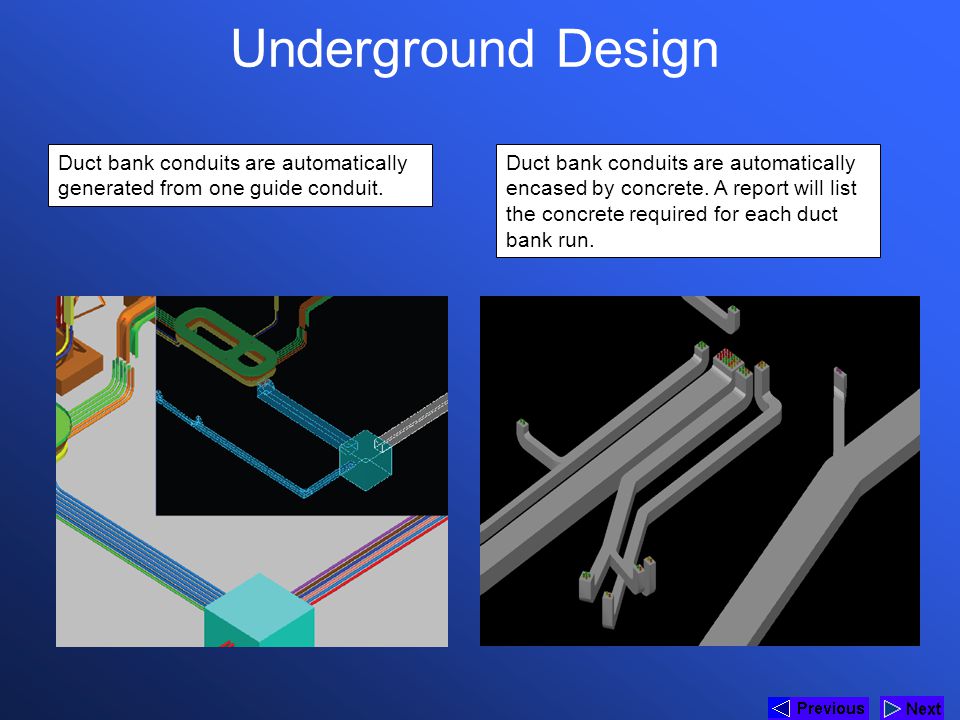
Concrete shall be red dyed utilizing red dye mixed into the concrete for a minimum of 5 minutes prior to pouring. 30 for secondary minimum 36 for primary minimum 48 maximum 10. Any secondary duct lengths. Service entrance mv and lv duct banks are to be concrete encased.
This section summarizes the design criteria for underground exterior electrical distribution systems. Underground concrete encased electric conduit duct banks shall consist of type db 60 polyvinyl chloride pvc conduit rated for 90 c cable and meeting nema standard tc 6 and astm f 512 for underground applications. Use bell adapters where conduits enter manholes. Contractor shall have class a 17 license for minimum of 2 years prior to work.
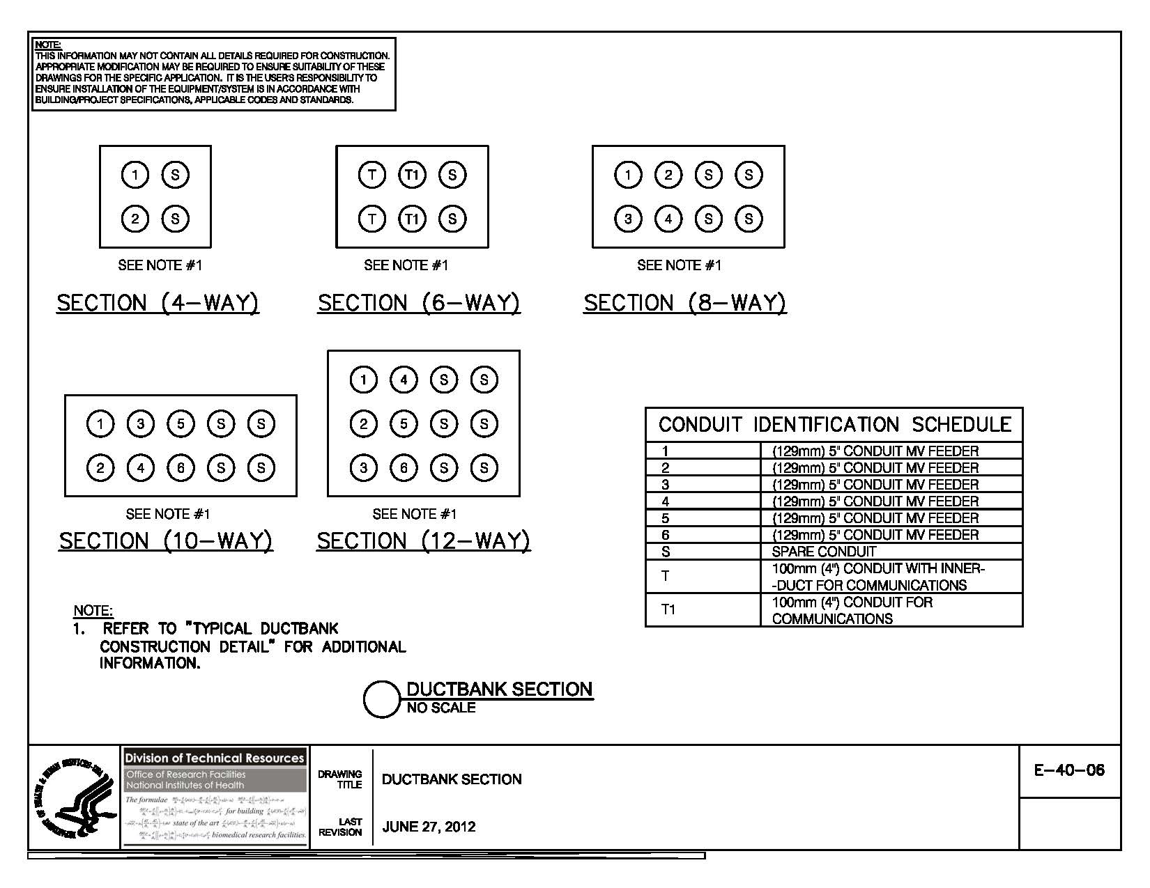
3 inches between ducts and exterior envelope wall between 2 inches ducts for like services and 4 inches between power and signal ducts. Minimum of 1 bag of dye per 1yd of concrete. Design all underground electrical raceways and duct banks for seismic zone 2. Minimum space between ducts.
System design and performance requirements 1. Use schedule 40 rigid pvc. Top of conduit conduit bank. The minimum allowable concrete duct compressive strength is 5 000 psi at 28 days.
In order to properly size the duct bank the following factors must be considered and evaluated. Electrical engineers designing electrical duct banks must understand the soil s thermal properties and the effects it will have on the overall installation. Ductwork standard design we can see from the velocity colour scale and the streamlines that in the design on the left the inlet air directly strikes the sharp turns that are present in the system which causes an increase in the static pressure.
